
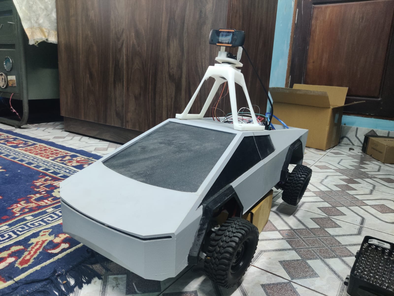
I made an autonomous CyberTruck with a Raspberry Pi

Imagine a construction site where materials are transported with ease and precision, freeing up workers to focus on the task at hand. Welcome to the future of construction, where technology meets innovation.
In this tutorial, we'll take you through the process of building ACAV, an Autonomous Construction Aid Vehicle that uses computer vision and machine learning to aid construction workers in transporting materials based on gestures from a supervisor. With a Raspberry Pi camera module, ArUco markers, and a pre-trained model, we'll show you how to bring this futuristic concept to life. Get ready to transform the construction industry with ACAV!
How it Works
The ACAV uses a camera to detect and recognize a supervisor based on the presence of an ArUco marker on their body as shown in the images below. Once the supervisor is identified, the ACAV uses computer vision to detect and interpret gestures made by the supervisor.

Current Capabilities
The ACAV currently recognizes two commands:
- Thumbs Up: The ACAV will follow the supervisor.
- Hi : The ACAV will stop.
These gestures allow the supervisor to control the ACAV's movements, enabling efficient and safe transportation of materials on the construction site.
Before We Begin...
Before we dive into the world of Autonomous Construction Aid Vehicles (ACAV), we recommend checking out Michael Rechtin's excellent video tutorial on building the cyber truck. This will give you a solid foundation in building the base vehicle, which we'll then upgrade with autonomous capabilities in this tutorial.
Once you've completed the cyber truck build, come back here and let's take it to the next level by adding computer vision and machine learning capabilities to create a fully autonomous ACAV!"
Additional Hardware Needed:
- Raspberry Pi 3B
- Webcam (for computer vision)
- PCA9685 (for servo control)
- Pc/Laptop (To run as server)
- Arduino (To control the motors)
3d printable items:
- Case for the PCA9685 module
- Case for the Raspberry Pi
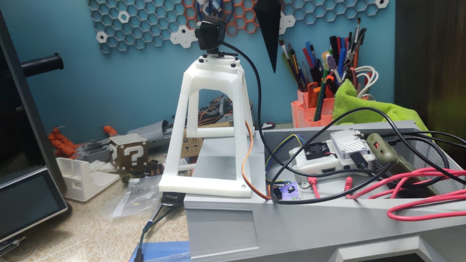
- Camera mount
Code Repository:
The complete code for this project is available on GitHub:
https://github.com/Dawn-Of-Justice/ACAV
Note:You can clone or download the repository to access the code and follow along with the tutorial.
Step-by-Step Instructions:

Step 1: Install and Set Up the Raspberry Pi
- Download the Raspberry Pi OS: Visit the official Raspberry Pi website and download the latest version of the Raspberry Pi OS (Raspbian) from the downloads page.
- Write the OS to the MicroSD Card: Use a tool like Etcher to write the Raspberry Pi OS image to your microSD card.
- Insert the MicroSD Card: Insert the microSD card into the Raspberry Pi 3B.
- Connect to Power: Connect the power supply to the Raspberry Pi 3B.
- Initial Setup: Connect to the Raspberry Pi using a keyboard, mouse, and monitor. Follow the on-screen instructions to complete the initial setup, including setting up the Wi-Fi network and creating a user account.
- Update the OS: Open the terminal and run the following command to update the Raspberry Pi OS:
sudo apt-get update && sudo apt-get upgrade
Step 2: Transfer the files from code/client-pi to raspberry pi

Instructions:
- Clone the Repository: Open a terminal on your computer and clone the GitHub repository using the following command:
git clone https://github.com/Dawn-Of-Justice/ACAV - Navigate to the Client-Pi Folder: Navigate to the
code/client-pifolder in the cloned repository. - Transfer the Files: Use a secure copy (SCP) or a file transfer protocol (FTP) client to transfer the files from the
client-pifolder to the Raspberry Pi.
Alternative Method:
If you don't have access to a computer, you can also use the Raspberry Pi's terminal to download the files directly from the GitHub repository. Run the following command: git clone https://github.com/Dawn-Of-Justice/ACAV
Step 3: Clone the Repository on Your PC
Objective: Clone the GitHub repository on your PC to access the necessary files for the server-side code.
Instructions:
- Open a Terminal: Open a terminal or command prompt on your PC.
- Clone the Repository: Clone the GitHub repository using the following command:
git clone https://github.com/Dawn-Of-Justice/ACAV - Navigate to the Server-PC Folder: Navigate to the
code/server-pcfolder in the cloned repository.
Step 4: Upload code to Arduino Uno

- Open the Arduino IDE: Open the Arduino Integrated Development Environment (IDE) on your computer.
- Select the Arduino Uno Board: Select the Arduino Uno board from the Tools menu.
- Upload the Code: Upload the code inside code/arduino/Motor-test to the Arduino Uno using the USB cable.
- Verify the Code: Verify that the code has been uploaded successfully and the Arduino Uno is functioning correctly
Step 5: Assemble the 3D Printed Parts
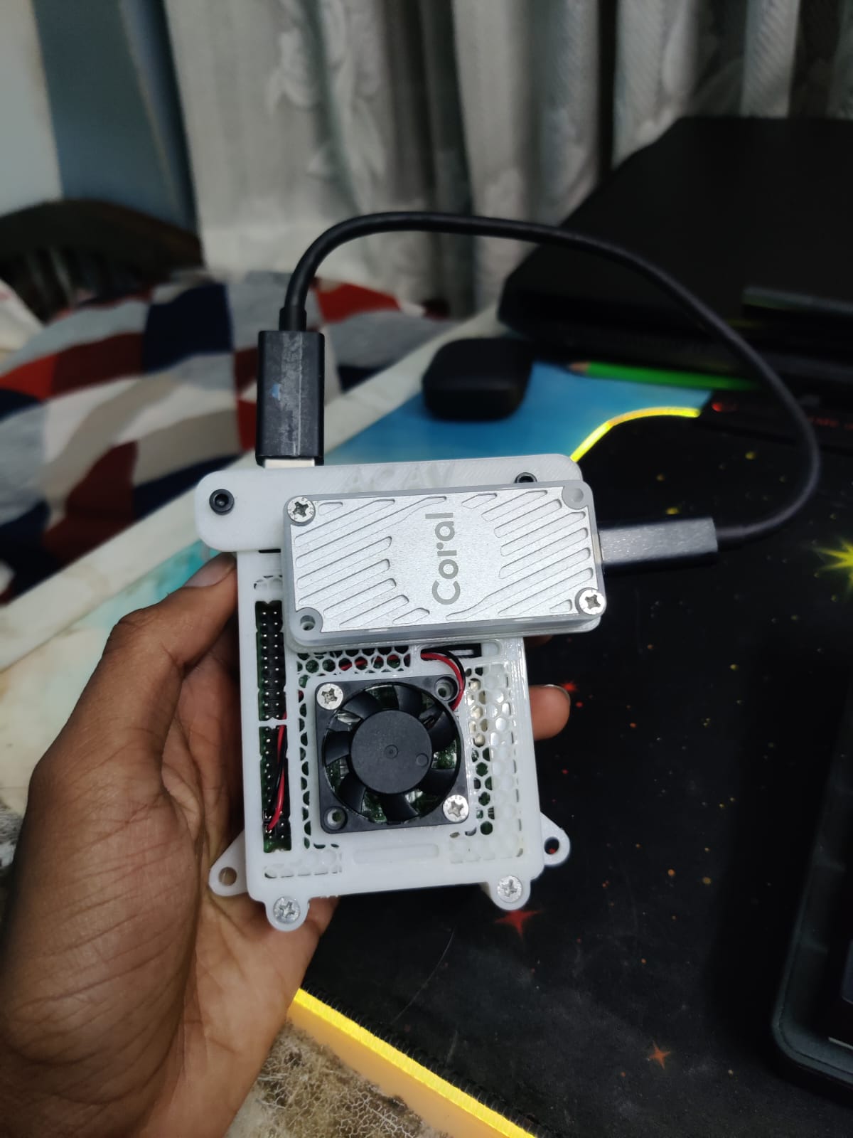
Note: In the image there is a coral TPU placed above the pi, We won't be using it .
Instructions:
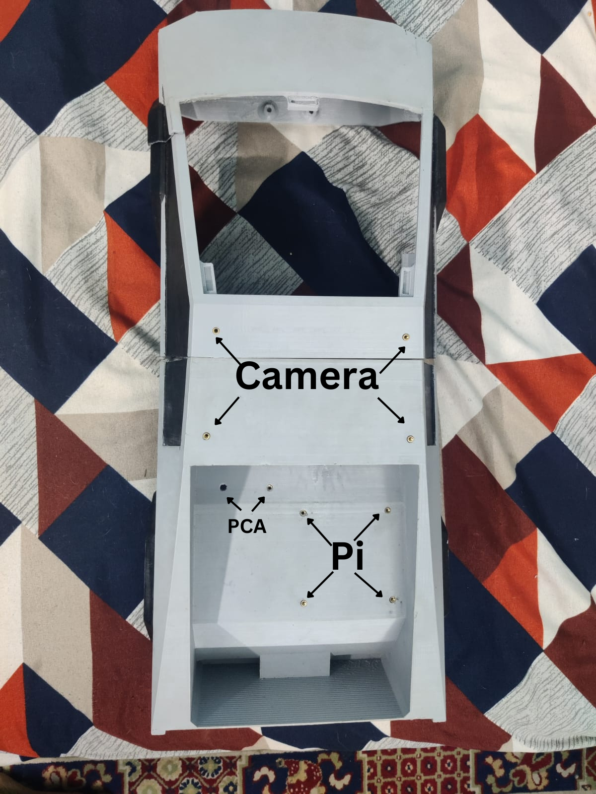
- Gather the 3D Printed Parts: Collect the 3D printed parts, including the camera mount, Raspberry Pi case, and PCA9685 holder.
- Assemble the Camera Mount: Attach the camera to the camera mount using the provided screws or adhesive.
- Mount the Raspberry Pi: Place the Raspberry Pi into the Raspberry Pi case and secure it with screws or clips.
- Mount the PCA9685: Attach the PCA9685 to the PCA9685 holder and secure it with screws or clips.
- Assemble the Components: Assemble all the components together, making sure they are securely attached and properly aligned.
Note: Since there are no holes in the body of the cyber truck, we will mount the components in the trunk of the car for now. Use a thread to hold the screw in place. Also do add additional screws for an arduino.
Step 6: Wiring
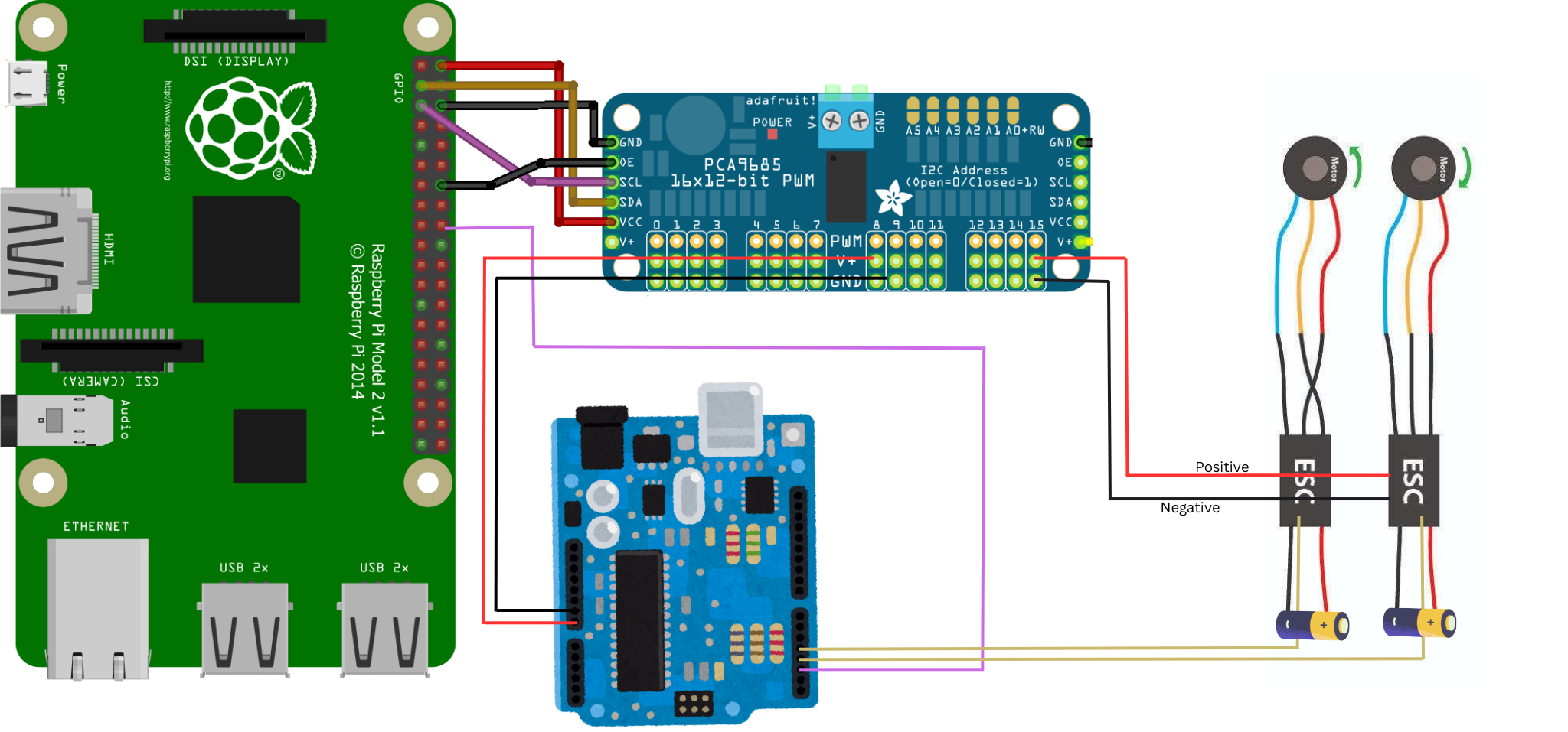
The Raspberry Pi has dedicated pins for I2C communication (GPIO2/GPIO3).
The module is equipped with an I2C bus and a power input. The I2C bus is connected as follows:
PCA9685 Connection
- GPIO3 or SCL pin to the SCL pin of the module
- GPIO2 or SDA pin to the SDA pin of the module
- 5V pin to Vdc pin of the module
- GND pin to GND pin of the module
Arduino Connection
- Arduino Pin 2 to pin 18 of Raspberry Pi
- Arduino Pin 3 to signal wire of front ESC
- Arduino Pin 4 to signal wire of rear ESC
- Arduino 5V to any positive terminal of PCA9685
- Arduino Ground to any ground terminal of PCA9685
Note: I am using arduino to control the motor, I tried to control directly from raspberry Pi but failed 🥲
- Connect the Servos from Cybertruck: Connect the servos from the Cyber truck to the PCA9685 module as follows:
- Channel 0: Connect the front servo from Cyber truck
- Channel 1: Connect the rear servo from Cyber truck
- Connect the Servo from camera: Connect the Servo from the camera to the PCA9685 module as follows:
- Channel 2: Connect the Servo from camera
- Channel 3: Connect the Servo from camera
- Connect the ESC: Connect the ESC from the motors to the PCA9685 module as follows:
- Connect both the Postive and Negative from the ESC to two ports of the PCA9685 as shown in the figure. (We use the esc to power the servo and arduino, altho it's not recommened but it will get the job done.)
Step 7: Connect the Battery and Calibrate the Motor
In this step, we'll connect the battery to the ACAV and calibrate the motor using the serial monitor.
Connect the Battery
- Connect the batterys to both the ESC
Calibrate the Motor
Note: During the calibration process, the wheels will spin at a very high speed. To avoid any accidents or injuries, please take the following precautions:
- Remove the wheels: Take off the wheels to prevent the car from moving unexpectedly.
- Hold the car securely: Hold the car firmly to prevent it from spinning out of control.
- Calibrate motors separately: Calibrate each motor individually to avoid both motors spinning simultaneously, which can be difficult to control.
- Open the serial monitor on your computer and connect to the Arduino Uno.
- Send the command
'2'to the Arduino Uno using the serial monitor. This will initiate the motor calibration process.
Step 8: Prepare the ArUco Marker
In this step, we'll prepare the ArUco marker that will be used to identify the supervisor.
Download the ArUco Image

- Download the ArUco image provided in the GitHub repository, located in images/aruco.png.
- Print out the image on a paper or cardstock.
Attach the ArUco Marker to the Supervisor's Shirt
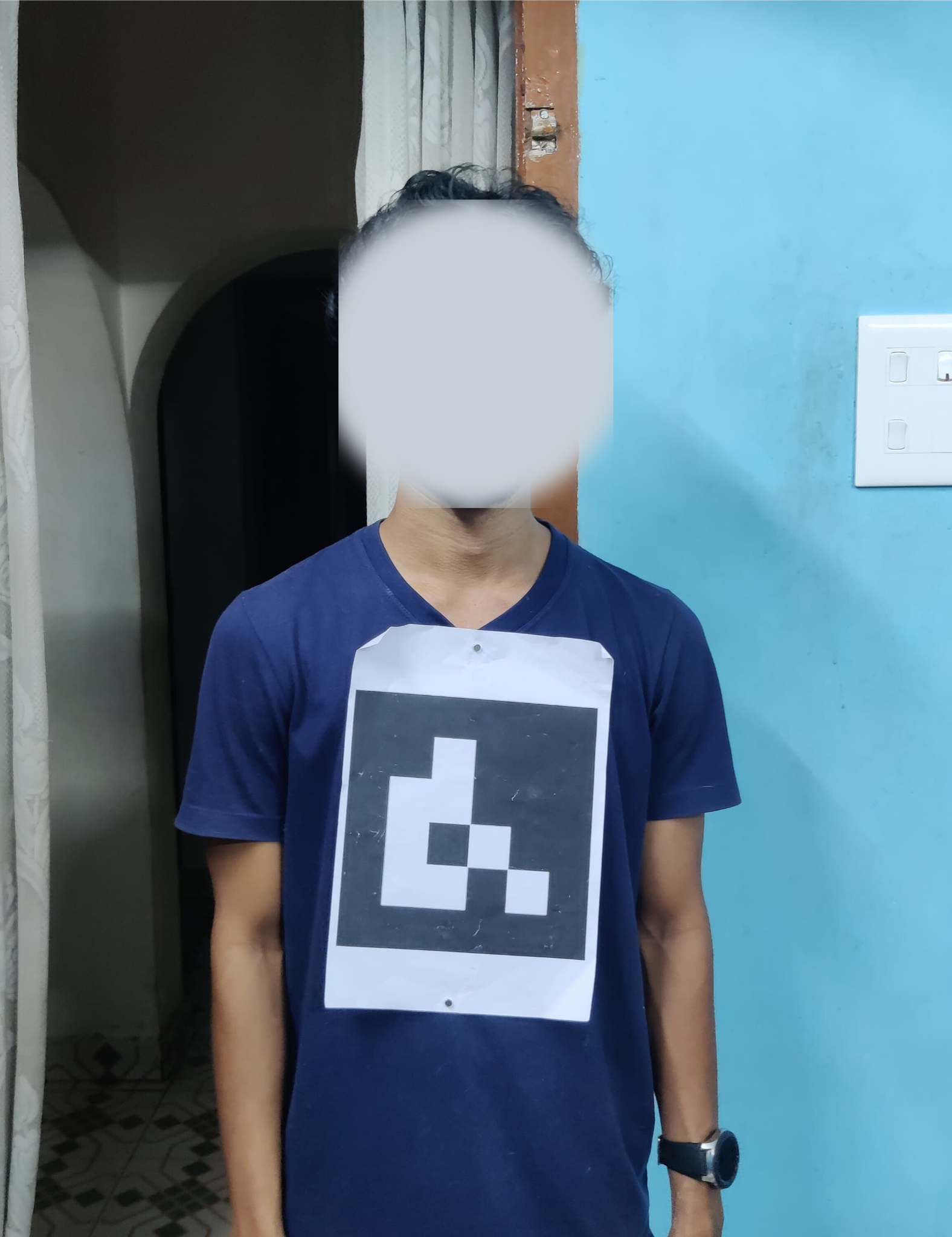
- Use a magnet, clip, or any other suitable method to attach the ArUco marker to the supervisor's shirt.
- Ensure the marker is securely attached and visible to the camera.
Step 9: Run the Client Script on the Raspberry Pi
In this step, we'll SSH into the Raspberry Pi and run the client script to connect to the server (PC).
Finding the IP Address of the PC
To find the IP address of the PC, you can use the ipconfig command in the Command Prompt on Windows or the ifconfig command in the Terminal on macOS/Linux.
On Windows:
- Press the Windows key + R to open the Run dialog box.
- Type
cmdand press Enter to open the Command Prompt. - Type
ipconfigand press Enter.
SSH into the Raspberry Pi
- Open a terminal on your computer and SSH into the Raspberry Pi using the following command:
ssh pi@raspberrypi(replaceraspberrypiwith the IP address of your Raspberry Pi). - Enter the password for the
piuser (default password israspberry).
Run the Client Script
- Navigate to the
code/client-pidirectory:cd code/client-pi - Run the
main.pyscript with the IP address of the server (PC) as an argument:python main.py <IP address of PC>
Example:
python main.py 192.168.1.100
Replace 192.168.1.100 with the IP address of your PC.
Note:
- Make sure the Raspberry Pi and PC are connected to the same network.
- Ensure that the IP address of the PC is correct and reachable from the Raspberry Pi.
Step 10: Run the PC Server
In this final step, we'll run the PC server to enable communication between the PC and the Raspberry Pi.
Run the PC Server
- Open a terminal or command prompt on your PC.
- Navigate to the
code/server-pcdirectory:cd code/server-pc - Run the
main.pyscript using Python:python main.py
What to Expect:
When you run the PC server, several windows will open:
- Camera (Live View): A window will open showing a live view from the camera.
- Gesture Detection: When the ArUco marker is detected, another window will open, displaying a skeleton view of the supervisor's gestures.
- SSH Terminal: When a valid gesture is detected (e.g., "go" command), the corresponding command (e.g., "Forward", "Stop", "Left", "Right") will be printed in the SSH terminal.
Here's an example of what the gesture detection window might look like:
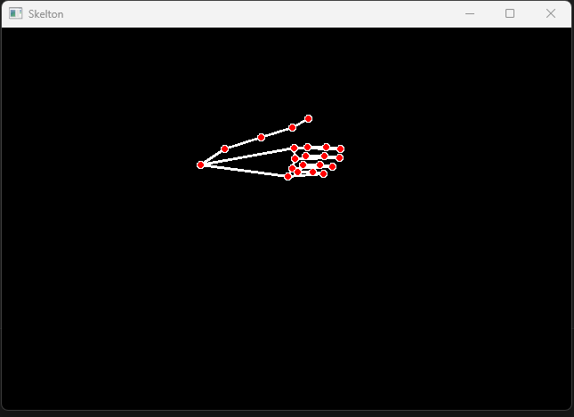
This is the detected hand gesture for go. By running the PC server, we'll enable the ACAV to receive commands from the supervisor and respond accordingly.
Result
After completing the tutorial, you should now have a fully functional Autonomous Construction Aid Vehicle (ACAV) that can recognize and respond to gestures from a supervisor.
In this demo, the supervisor is wearing an ArUco marker on their shirt, which is detected by the Raspberry Pi camera module. The ACAV then recognizes the supervisor's gestures, such as "thumbs up" to move forward or "waving" to stop. The ACAV responds accordingly, moving forward or stopping as commanded.
Conclusion
Congratulations! You have now successfully built an Autonomous Construction Aid Vehicle (ACAV) that uses computer vision and machine learning to aid construction workers in transporting materials. The ACAV can recognize and respond to gestures from a supervisor, enabling efficient and hands-free control of the vehicle.
Congratulations on completing the Autonomous Construction Aid Vehicle (ACAV) tutorial! If you have any questions or need further clarification on any of the steps, please don't hesitate to ask in the comments section below. We're here to help!


Comments